null

Top 5 Cell Signal Booster Vehicle Antennas for 2024

Antennas for car, truck, & SUV cell phone signal booster systems from Powerful Signal

COMPARISONS

Large home • Small home • Car & truck • Vehicle antennas

Updated

Need to improve your cell signal booster’s reception on the road?

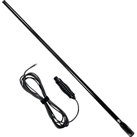
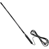
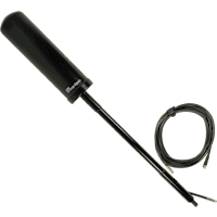
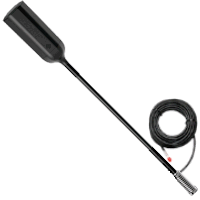
A mobile cell signal booster can only amplify the signal that it receives from its external donor antenna. Adding a higher-gain donor antenna to your cellular booster system can improve the booster’s performance and allow you to travel in more remote areas with weak outside cell signal.

Powerful Signal has tested the top mobile cell phone signal booster antennas from leading manufacturers. Here are our top five recommended antennas for this year, sorted by price:
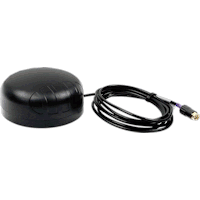
ANTENNA
RFI 38″ Q-Fit Whip
RFI 26″ Whip
Top Signal 5G OTR
Wilson Drive OTR
Poynting PUCK-1
RFI 38-Inch Quick-Release Whip Vehicle Antenna CDQ7195-B
RFI 26-Inch Whip Vehicle Antenna CD7194-B
Top Signal 5G OTR Antenna TS210401
Wilson Drive OTR Antenna 311229
Poynting PUCK-1 5G/LTE Antenna A-PUCK-0001-V1-01
SKU
TS210701
TS210513
TS210401
311229
TS210616
Price
RFI 38″ Q-Fit Whip: $249.99
RFI 26″ Whip: $199.99
Top Signal 5G OTR: $119.99 $99.99 sale price
Wilson Drive OTR: $119.99
Poynting PUCK-1: $69.99
Powerful Signal’s Evaluation
RFI 38″ Q-Fit Whip: Highest gain¹ & quick-release takedown feature
RFI 26″ Whip: Performance nearly as good as the 38″ at a lower price
Top Signal 5G OTR: Highest gain w/variable mast length; shorter cable for less excess in vehicles
Wilson Drive OTR: Best option to clear high truck cabs
Poynting PUCK-1: Best low-profile option; most standard mounting options; better at high frequencies
Mast extensions
RFI 38″ Q-Fit Whip:
RFI 26″ Whip:
Top Signal 5G OTR: ×1 (11.1″)
Wilson Drive OTR: ×2 (18″ & 13″)
Poynting PUCK-1:
Height
RFI 38″ Q-Fit Whip: 38.2″ (97.0 cm)
RFI 26″ Whip: 25.8″ (65.5 cm)
Top Signal 5G OTR: 11.5″, 15.2″, 22.5″, 26.3″ (30.2, 39.6, 58.2, 67.8 cm)
Wilson Drive OTR: 13.5″, 26.5″, 31.5″, 41.5″ (34.3, 67.3, 80.0, 105.4 cm)
Poynting PUCK-1: 1.4″ (3.6 cm)
Max. Width
RFI 38″ Q-Fit Whip: 1.7″ (4.3 cm) @ spring base
RFI 26″ Whip: 1.3″ (3.2 cm) @ spring base
Top Signal 5G OTR: 2.6″ (6.6 cm) @ radome base
Wilson Drive OTR: 2.7″ (6.8 cm) @ radome top
Poynting PUCK-1: 3.9″ (9.9 cm)
Mount (standard)
RFI 38″ Q-Fit Whip: Threaded spring base; mount not included
RFI 26″ Whip: Attached spring base; mount not included
Top Signal 5G OTR: Spring base w/L-bracket 3-way mount; free 180° swivel fold-down mount
Wilson Drive OTR: Spring base w/3-way mount
Poynting PUCK-1: Magnet; adhesive; spigot (×2); pipe; wall; panel
Mount (optional)
RFI 38″ Q-Fit Whip: Rail; magnet; Rhino-Rack; bull bar; SkyPole
RFI 26″ Whip: Rail; magnet; Rhino-Rack; bull bar; SkyPole
Top Signal 5G OTR: Magnet; Rhino-Rack
Wilson Drive OTR: Magnet; Rhino-Rack
Poynting PUCK-1: n/a

Nominal Gain,² dBi

RFI 38″ Q-Fit Whip
RFI 26″ Whip
Top Signal 5G OTR
Wilson Drive OTR
Poynting PUCK-1
600–798 MHz
RFI 38″ Q-Fit Whip: 6.5
RFI 26″ Whip: 5.0
Top Signal 5G OTR: n/a
Wilson Drive OTR: 1.4
Poynting PUCK-1: n/a
806–960 MHz
RFI 38″ Q-Fit Whip: 6.5
RFI 26″ Whip: 5.0
Top Signal 5G OTR: n/a
Wilson Drive OTR: 2.4
Poynting PUCK-1: n/a
1710–1880 MHz
RFI 38″ Q-Fit Whip: 4.5
RFI 26″ Whip: 4.5
Top Signal 5G OTR: n/a
Wilson Drive OTR: 3.1
Poynting PUCK-1: n/a
1990–2170 MHz
RFI 38″ Q-Fit Whip: 4.5
RFI 26″ Whip: 4.5
Top Signal 5G OTR: n/a
Wilson Drive OTR: 2.4
Poynting PUCK-1: n/a
2300–2700 MHz
RFI 38″ Q-Fit Whip: 5.5
RFI 26″ Whip: 5.5
Top Signal 5G OTR: n/a
Wilson Drive OTR: 2.6
Poynting PUCK-1: n/a
3300–4000 MHz
RFI 38″ Q-Fit Whip: n/a
RFI 26″ Whip: n/a
Top Signal 5G OTR: n/a
Wilson Drive OTR: n/a
Poynting PUCK-1: n/a

Peak Gain,³ dBi

RFI 38″ Q-Fit Whip
RFI 26″ Whip
Top Signal 5G OTR
Wilson Drive OTR
Poynting PUCK-1
600–798 MHz
RFI 38″ Q-Fit Whip: n/a
RFI 26″ Whip: n/a
Top Signal 5G OTR: 3.3
Wilson Drive OTR: 2.4
Poynting PUCK-1: −1.0
806–960 MHz
RFI 38″ Q-Fit Whip: n/a
RFI 26″ Whip: n/a
Top Signal 5G OTR: 3.2
Wilson Drive OTR: 2.6
Poynting PUCK-1: −1.0
1710–1880 MHz
RFI 38″ Q-Fit Whip: n/a
RFI 26″ Whip: n/a
Top Signal 5G OTR: 4.1
Wilson Drive OTR: 3.8
Poynting PUCK-1: 7.0
1990–2170 MHz
RFI 38″ Q-Fit Whip: n/a
RFI 26″ Whip: n/a
Top Signal 5G OTR: 3.9
Wilson Drive OTR: 3.7
Poynting PUCK-1: 7.0
2300–2700 MHz
RFI 38″ Q-Fit Whip: n/a
RFI 26″ Whip: n/a
Top Signal 5G OTR: 3.4
Wilson Drive OTR: 4.3
Poynting PUCK-1: 7.0
3300–4000 MHz
RFI 38″ Q-Fit Whip: n/a
RFI 26″ Whip: n/a
Top Signal 5G OTR: 2.3
Wilson Drive OTR: n/a
Poynting PUCK-1: 8.0
RFI 38″ Q-Fit Whip
RFI 26″ Whip
Top Signal 5G OTR
Wilson Drive OTR
Poynting PUCK-1
VSWR
RFI 38″ Q-Fit Whip: <2.5:1
RFI 26″ Whip: <2.5:1
Top Signal 5G OTR: n/a
Wilson Drive OTR: <2.0:1
Poynting PUCK-1: ≤2.5:1
Coax Cable
RFI 38″ Q-Fit Whip: 16.4′ (5.0 m) RG58
RFI 26″ Whip: 16.4′ (5.0 m) RG58
Top Signal 5G OTR: 11.3′ (3.4 m) RG58
Wilson Drive OTR: 16′ (4.9 m) LMR195
Poynting PUCK-1: 6.6′ (2.0 m) RTK031
Connector
RFI 38″ Q-Fit Whip: SMA-male
RFI 26″ Whip: FME-female
Top Signal 5G OTR: SMA-female w/SMA-male adapter
Wilson Drive OTR: SMA-female w/SMA-male adapter
Poynting PUCK-1: SMA-male
Return Policy
RFI 38″ Q-Fit Whip: 90 days
RFI 26″ Whip: 90 days
Top Signal 5G OTR: 90 days
Wilson Drive OTR: 90 days
Poynting PUCK-1: 90 days
Manufacturer’s Warranty
RFI 38″ Q-Fit Whip: 1 year
RFI 26″ Whip: 1 year
Top Signal 5G OTR: 90 days
Wilson Drive OTR: 90 days
Poynting PUCK-1: 2 years

Notes

¹ Gain describes how well the antenna diverts, directs, or concentrates radio waves into electrical power (when it’s receiving) and electrical power into radio waves (when it’s sending). (Learn moreexternal link icon.) Antenna gain is measured in decibels (isotropic) (dBi), which is the gain of the antenna compared to the gain of a theoretical isotropic antennaexternal link icon that uniformly distributes energy in all directions, calculated in decibelsexternal link icon. The decibel scale is logarithmic: An increase of 3 dBi is double the gain, an increase of 10 dBi is ten times the gain, and an increase of 20 dBi is one hundred times the gain.

² Omnidirectional antennas send and receive signal in all directions, but they have more gain (are more efficient) in some directions and have less gain (are less efficient) in others. Nominal gain is the average of the antenna’s gain in all directions. Some directions will have higher than nominal gain (see peak gain, below); other directions will have less than nominal gain. Some antenna manufacturers prefer to publish peak gain figures instead of nominal gain figures.

³ Peak gain is an omnidirectional antenna’s maximum gain in its most efficient direction. Since the direction of peak gain may not be the direction of the cell tower, peak gain figures should be used cautiously; an antenna will most often not be sending/receiving at peak gain. Some antenna manufacturers prefer to publish nominal gain figures instead of peak gain figures.

 Negative gain indicates that the antenna does not radiate as well as a theoretical isotropic antennaexternal link icon. The antenna still sends and receives at this frequency range; it’s just not as efficient in a range where it has negative gain. Small antennas are often only efficient in a narrow frequency range and more susceptible to having negative gain outside that range.

 Voltage Standing Wave Ratio (VSWR, “viz-wer”) is a ratio that describes how well the antenna’s impedance is matched to the impedance of its transmission line (coaxial cable). The lower the first number in the ratio, the more power is delivered and the less is reflected. A VSWR of 1.5:1 is better than 2:1, and a VSWR of 2:1 is better than 3:1. (Learn moreexternal link icon.)

 Powerful Signal offers a 90-day return on most products. (See our complete return policy.)