Knowledge Base
What is VSWR and how does it affect antenna performance?
Most antenna manufacturers include a VSWR figure in their antenna specifications. This article will explain, in simple terms, what VSWR is and how it can help you evaluate an antenna’s performance for your cell signal booster or cellular router.
A brief explanation of VSWR
An antenna sends and receives signal to and from a cellular booster, router, or other device. It does not, however, send all the signal it receives; some of that signal is reflected back to the source.
An antenna’s VSWR figure tells you how much of the signal it receives is reflected back. All other things being equal, an antenna with a lower VSWR number is going to deliver more signal to your booster or router.
A deeper explanation of VSWR
Impedance
Impedance is the opposition to the flow of electrical current as it moves through a circuit, a wire, a coaxial cable, or an antenna.
An antenna’s impedance differs—often substantially—by frequency; because of this, most antennas are designed to operate in a specified frequency range with acceptable impedance levels. Using an antenna outside of its intended frequency range results in overly strong impedance and signal reflection, so you should always use the right antenna for the right frequency.
Return loss
If the impedance of an antenna and the cable connected to it are different, part of the feeding signal (or forward power) is reflected (reverse power). Reflected power is almost always undesirable.
Return loss is the portion of the input power reflected from the antenna due to impedance mismatch.
VSWR
The feeding signal (forward power) and the reflected signal (reverse power) combine into a single wave called a standing wave.
In this animation, the green wave is the forward power, the red wave is the reflected power due to impedance mismatch, and the blue wave is the resulting standing wave:
 Animation courtesy of Fred Cirera, 0x9900.com. Used with permission.
VSWR (Voltage Standing Wave Ratio, “viz‑whar”) is the ratio of the maximum (Vmax) and minimum (Vmin) voltage of the standing wave:
| Vmax |
| Vmin |
In the animation above, Vmax = 1.5 and Vmin = 0.5, so:
| 1.5 |
| 0.5 |
…or, expressed as a ratio, 3:1.
Ideally, the impedance of the antenna and the cable would be exactly equal, resulting in a VSWR of 1:1 with zero signal reflection. If VSWR is 2:1, there is a mismatch and some of the input signal is reflected. If it’s 3:1, there is an even greater mismatch, and so on.
An antenna’s VSWR figure will vary by frequency. Many manufacturers will give the highest VSWR figure across all the frequencies the antenna is designed for and state that the VSWR will be less than (<) or less than or equal to (≤) that number. For example:

Other manufacturers will state the antenna’s VSWR at various frequencies

S11 (reflection coefficient)
S11—also known as the reflection coefficient and expressed as the Greek letter Gamma (Γ)—is the ratio of the voltage wave reflected from the antenna port to the input voltage wave.
We won’t go too deep into S11; you can learn more about it in the Further reading section, below. We’re introducing it just so you can determine how much signal is reflected back at various VSWR figures.
First, we need to convert VSWR to S11:
| VSWR −1 |
| VSWR +1 |
Using our example above of an antenna that has a VSWR of 3:
| 3 −1 |
| 3 +1 |
| 2 |
| 4 |
To determine what percentage of power is reflected, square the absolute value of S11:
Reflected power = |Γ|2
Using our example:
|Γ|2 = 0.52 = 0.25 = 25%
So, an antenna with a VSWR of 3 will reflect back 25% of the signal it receives. Keep in mind that’s the antenna’s VSWR varies across all the frequencies it’s designed for, so it’s possible that it’s reflecting less or more than 25% at a different frequency than the one we measured.
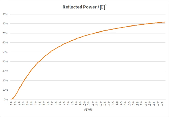
Using those formulas, we can determine how much signal is reflected back at different levels of VSWR:
Because the percentage of power reflected is equal to the square of S11, power reflected is logarithmic:

Why is VSWR important?
When comparing two antennas with the same amount of signal gain, the antenna with lower VSWR numbers in key cellular frequencies is going to deliver more signal to your booster or router.
Further reading
If you’d like to learn more about VSWR, here are some suggested resources that will give you more information:
- RF elements s.r.o, “Inside Wireless: VSWR, |S11|, Return Loss,” YouTube (2:49 video), 19 October 2019.
- Rohde Schwarz, “Understanding VSWR and Return Loss,” YouTube (10:09 video), 18 October 2019.
- Fred Cirera, “Reflected Power and VSWR,” 0x9900 (blog post), 25 April 2021.
- Peter Joseph Bevelacqua, “S-Parameters,” Antenna Theory.
- “VSWR and Return Loss Calculations,” A. H. Systems, 2023.

